
One of the things lacking in my shack for the longest time has been a dependable and traceable frequency reference for checking my radios' frequency alignment and any other application requiring an accurate frequency reference. The Leo Bodnar Electronics Mini Precision GPS Reference Clock has been available for a few years and I finally took the plunge to order one in late January.

After dropping roughly C$230.00 (inclusive of taxes, duties and FedEx shipping), the unit arrived in my mail box one week later. In the box is the unit itself, an active GPS patch antenna with a 5 metre cable and a 1 metre USB-A to USB-mini cable for connection to a computer. There are no instructions with the unit, presumably that whoever orders one of these knows what it's for and has a good idea of how to use it. The unit draws 250 mA. from the USB connection for power; configuration is done with a custom freeware tool that runs on Windows® and is available from the Leo Bodnar web site. The link for the software isn't particularly easy to find but it is there. A MacOS version is available from the Apple Store; there is no Linux version that I'm aware although a trip to GitHub might turn up something.
It's important to realise that the USB interface to the unit is USB-mini; not -micro as is usual on smart phone and other consumer device USB cables. USB-mini cables aren't too common in my experience, the only other device I've found using it is higher-end DSLR cameras. The USB-mini is more mechanically robust than -micro and I suppose that's why it's implemented on this unit. In any case, be aware of this and safeguard the cable if you don't have others.
The clock unit itself is small, measuring 40 x 70 x 15 mm., being only slightly larger than the accompanying GPS active antenna.
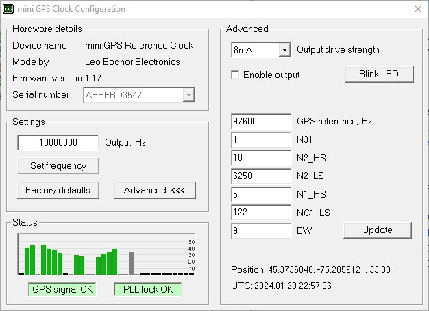
Setting up the unit for operation is simple: connect the GPS antenna, connect a 50 Ω termination on the unit's output, connect the USB cable to your Windows® computer and wait for the plug & play setup operation to complete. Launch the mini-GPS configuration software and it should come up with a window showing the unit serial number and firmware revision along with the operating controls and diagnostics. Having the unit serial number show in the Hardware Details indicates the configuration software is connected to the unit. It takes about 30 seconds for the GPS to lock up; there are indicators on the configuration window showing GPS acquistion (red or green) along with the number of satellites being received, and the oscillator PLL lock status (red or green). Once both GPS and PLL are green the unit is ready to deliver the GPS-disciplined clock output.
The unit does run a bit warm which is an indicator that the TCXO temperature stabilisation is working. There is a red LED beside the unit's clock output jack which is lit when the output is active. The LED will blink if the oscillator is free-running without GPS lock. Once configured, the unit will run without a computer, needing only a USB power source. The unit will retain its state when powered off. Unfortunately there is no hardware switch on the unit to control the RF output on-off state. I'd suggest terminating the output in either an SMA load or the target device before restoring power; the Leo Bodnar web site says nothing about clock output tolerance to an open circuit.
As for signal stability and purity specs, you can look them up on the Leo Bodnar web site:
The Allan Deviation chart shows a short term frequency uncertainty of 5x10-11 which, at 500 MHz., would present a frequency uncertainty of 0.025 Hz. Good enough for most ham applications I'd say.
So, enough with the specs on the unit - now to put it to use. About a year ago, a new IC-705 came to my door and one of the first things I did was to check its frequency accuracy against WWVH-25 MHz. (Rambler - March 2023) finding that an adjustment from the as-delivered value of 47% to 52% was necessary to bring the radio closer to the mark. Going through this exercise again one year later, with the GPSDO providing a signal at 440.000000 MHz., another IC-705 adjustment from 52% to 57% was in order. Great - so now the IC-705 is a close as I can get it short of having it run from an external reference (which isn't possible with the 705). The same exercise was done with my Yaesu FT-991A, finding a slight tweak to its reference would bring it into line. Finally, a check on my faithful 25 year old Kenwood TS-850SAT showed it to be about 90 Hz. high at 29.000000 MHz. Not worth the effort of disconnecting all the cables, lifting the covers and risking a twist of the frequency reference trimmer.
More inquiring readers might ask what parameters I used to precisely trim the radio oscillators from simply receiving the GPSDO signal. Well, it depends on the operating features of the radio.
For the Yaesu FT-991A, it was rather simple. Set the receive mode to CW and engage the "ZIN" zero beat control which automatically tunes the radio's RF to achieve the user-defined CW sidetone frequency. Adjust the radio's reference until zero-beating results in a dial frequency exactly the same as the test signal. With the FT-991A, the resolution of the display is 10 Hz. so zero beating can bring the radio to within ±5 Hz. of centre.
The IC-705 can be adjusted two ways: using the CW AutoTune function or by zeroing the audio tone received in USB mode. I found the Autotune/CS-RX function to be a bit finicky and had to press it a few times to be sure of a repeatable result. I then turned to the second method of setting the receive mode to USB and launching the "Audio Scope" front panel display to show the demodulated audio spectrum. A low audio frequency component indicates the RF frequency is slightly off so the ideal condition is when the low frequency audio tone JUST disappears. See the following photographs:

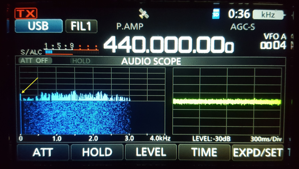

A quick check back with the Autotune/CS-RX confirmed the radio's alignment with the GPSDO.
That brings us to the TS-850 which has neither a zero beat function nor a spectrum display. Well, with the help of a smart phone and a musical instrument tuner app, one can do the same kind of CW tone check as with the FT-991A. Adjust the radio to the test signal frequency, in this case 29.000000 MHz., and set the receive mode to CW. An audio beat tone should appear, in my case it was set to 700 Hz. and measuring the tone's audio frequency tells me how closely the radio is tuned at RF. For the 25 year old TS-850, I measured 788 Hz. instead of 700 Hz.; not bad for old faithful. I suppose another way to do this would be to set the GPSDO to 29.000440 MHz. and listen for the beat tone between the radio's audio and a Standard-A tuning fork.
I also have a Hewlett-Packard 5383A frequency counter good up to around 500 MHz. acquired as-is at a ham flea market many years ago. Checking it against the GPSDO revealed that it's internal oscillator isn't very stable at all and could have an uncertainty of ±200 Hz. at 10 MHz. even after a 12 hour warmup. Not very good, so now I know the counter is still useable but needs an external lock to the GPSDO for accurate readings.
It should be understood that the Leo Bodnar GPSDO is aclocksource and not an RF signal generator, meaning that its output is a square wave rather than a sinusoid. Knowing that, it should be kept in mind that radiating RF signals from this unit directly to air will also radiate many harmonics of the fundamental. For tuning accuracy checks of ham radios, this isn't really a problem since only the fundamental is received by the radio, but be aware.
The mini-GPS has a specified frequency adjustment range of 400 Hz. - 810 MHz. which is certainly a wide enough range for most ham requirements. Next step is to find an audio amplifier, set the GPSDO output to 440 Hz. and start tuning pianos.
73, Hugo Kneve - VE3KTN