
According to Innovation, Science and Economic Development (ISED) Canada “… The "amateur radio service"..is a radio communication service in which radio apparatus are used for the purpose of self-training, intercommunication or technical investigation by individuals who are interested in radio technique solely with a personal aim and without pecuniary interest…”.
This emphasis on technological advancement and experimentation in the amateur radio community has rapidly developed with the advent of Software Defined Radio (SDR). QST’s working definition of SDR was that: “… A Software (Defined) Radio is one in which one or more transceiver functions are performed by digital circuitry under software control on a digital representation of the signal. Software radios use digital signal processing (DSP) for filtering, modulation and demodulation of signals within the radio. DSP can do everything an analog radio can do, it can also do functions that are difficult or impossible for analog radios… ” (QST, Oct 2002, pages 33-35).
The availability of powerful microprocessors in combination with software developments in the last 20 years, is the driving force behind the resurgence in building sophisticated QRP (low power) HF transceivers. Traditional amateur radio analogue transceivers often had a bandpass range of just 3 KHz. Typical amateur radio SDRs can cover all frequencies from 1 kHz through VLF, LF, MW, HF, VHF, UHF and L-band to 2 GHz, with no gap. With digital communications and new digital modes, SDR receiver software can evolve for the use of new digital modes. As such software improvements and innovations increase the possible range of amateur radio uses of your SDR.
One such innovation is that of CW skimmer, which I will describe in the context of the Reverse Beacon Network (RBN) and Software Defined Radio.
CW Skimmer: There have been many attempts to develop computer programs to decode individual CW signals on the air. CW decoders, such as those included on Elecraft KX3, only copy one signal, which YOU tuned to. In 2008 CW Skimmer (Alex Shovkoplyas, VE3NEA) became available and can best be described as “… a high sensitivity CW decoding algorithm based on the methods of Bayesian statistics; simultaneous decoding of ALL CW signals in the receiver passband - up to 700 signals can be decoded in parallel on a 3-GHz P4 if a wideband receiver is used; a fast waterfall display, with a resolution sufficient for reading Morse Code dots and dashes visually; the callsigns are extracted from the decoded messages, and the traces on the waterfall are labelled with stations' callsigns; the extracted callsigns are exported as DX cluster spots via the built-in Telnet cluster server; a DSP processor with a noise blanker, AGC, and a sharp, variable-bandwidth CW filter; an I/Q Recorder and player.”
With the advent of CW Skimmer, amateur radio stations were now able to automatically update the SDR data to various amateur radio servers and combine their data with other contributors. The CW Skimmer program was modified for use by server grade computers and from several SDRs simultaneously to provide a comprehensive picture across the CW sections of amateur radio bands.
Some CW skimmer stations monitor up to 192 KHz of individual amateur radio bands to detect various signals. Wideband display and decoding shown in Figure 1 require a wideband SDR receiver. By way of comparison please note that only 3 KHz of spectrum can be decoded and viewed on the waterfall display if a typical 3 KHz band width radio is used, as shown on the Figure 2 screenshot. In both cases the call signs detected are validated with a database of known amateur radio calls before being sent to the Reverse Beacon Network.
Reverse Beacon Network: Now let’s look into how the system of CW skimmers, Software Defined Radio and the Reverse Beacon Network have evolved over the years. This system of world wide networked receivers are able to provide live real-time data that is supplied by telnet to the Reverse Beacon Network.
The original networked CW skimmer stations were very expensive to create and operate. The original K3LR contest station hardware (see Figure 3,4) illustrates a multi-band first generation CW skimmer station that consisted of rack mounted six (6) server grade computers of multi-core high performance computers hand built by W9PA. The computers required a custom monitored power supply. The first generation system used six (6) Perseus SDR HF receivers to simultaneously supply up to six band data to the RBN (see Figure 5).
The second generation of the K3LR CW skimmer hardware replaced the six servers with six (6) Intel NUC mini computers which are small form factor PCs. Intel NUC (Next Unit of Computing) are multi-core high performance 13.8 VDC computers. The second generation system continues to use the six (6) Perseus SDR HF receivers to simultaneously supply up to six band data to the RBN. The second generation system uses three additional Intel NUC mini computers to continuously backup all the data that is being sent to the Reverse Beacon Network (see Figures 5,6,7,8,9).
Finally, at the time of writing this article in January 2023, a current RBN Node list is shown in Figure 10. There were 208 skimmers online, 3 new skimmers in the last 7 days, 211 skimmers online in the last hour, 230 skimmers online in the last 24 hours, 263 skimmers online in the last 7 days, and 3159 skimmers online since the project began. This is truly a crowd sourced volunteer project!
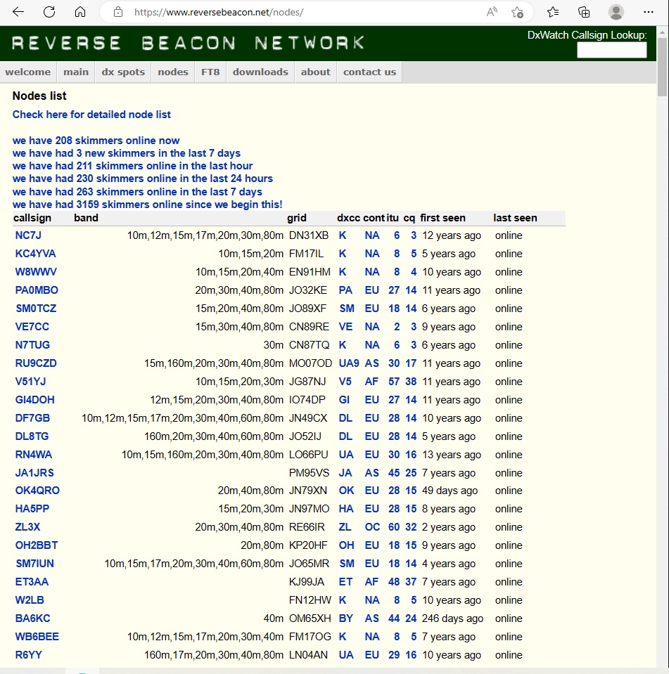
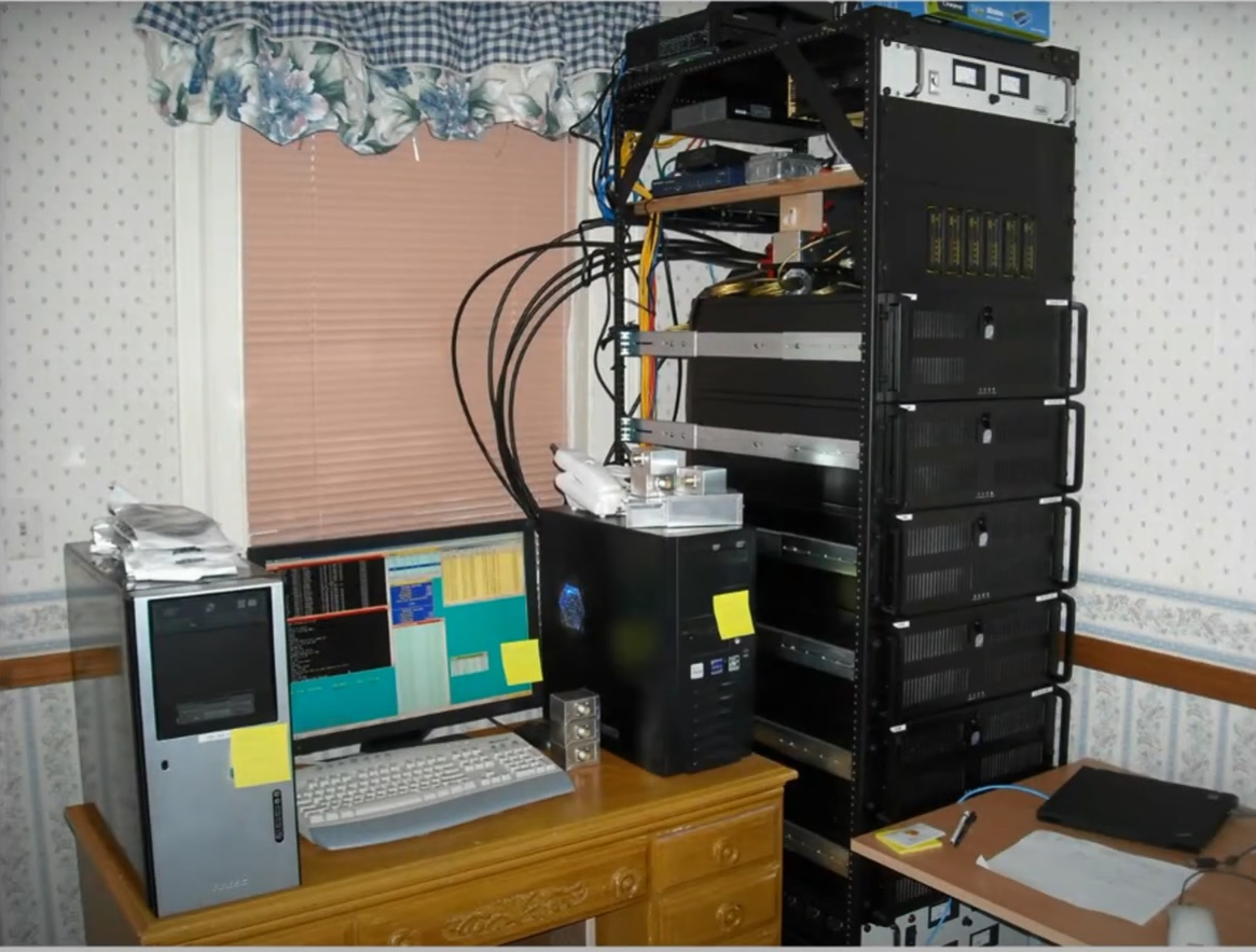
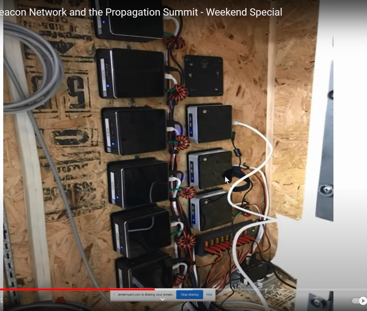
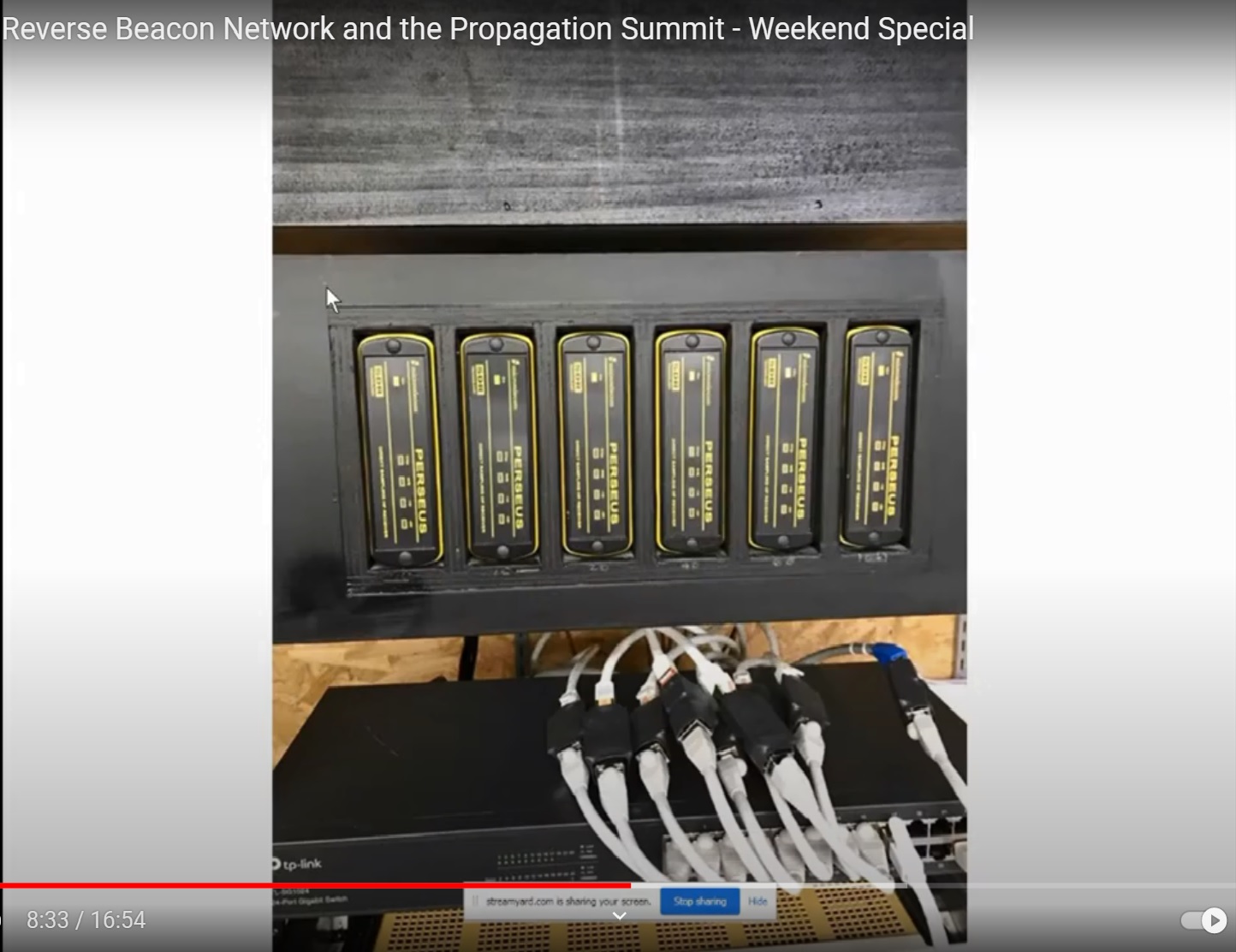
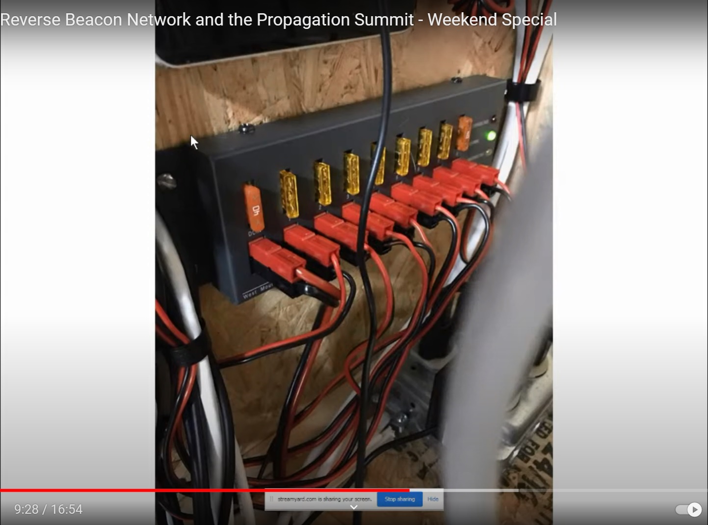
Figure 7: The Second generation K3LR CW skimmerhardware evolved to use 13.8 VDC to power the six (6) Intel NUC mini computers which have replaced six multicore servers. A West Mountain individually fused DC power supply system using Anderson Power Pole connectors is used to power the NUC computers. Note: This image demonstrates good amateur radio practice in using appropriately rated fuses for each circuit to provide the best protection for each individual NUC. Image credit K3LR
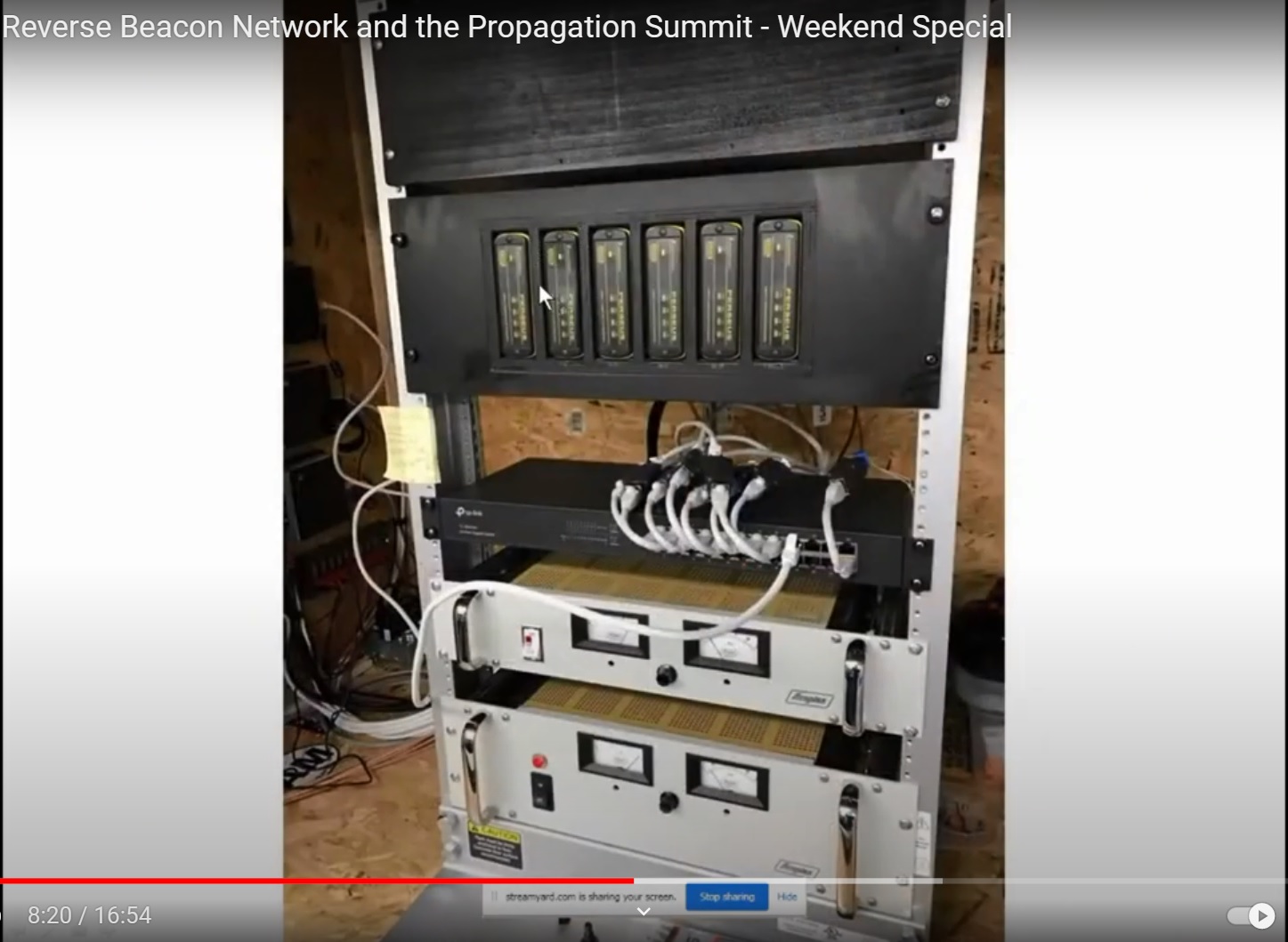
Figure 8: The Second generation K3LR CW skimmer hardware now uses two dedicated commercial power supplies to provide 5 VDC for the six (6) Perseus SDR HF receivers and 13.8 VDC for the (6) Intel NUC mini computers and (3) extra NUC mini computers used for data backup.
I hope that this detailed look at a typical Reverse Beacon Network node station equipped with CW skimmer software and hardware, SDR receivers and dedicated HF antenna will provide a hint of the cost and dedication required to provide the continuous source information to feed into the RBN. One of the challenges of operating the RBN is the large number of volunteers needed to provide the data. There are many areas of the world where there are no RBN stations to provide the data. Recently there have been projects to fund various amateur radio clubs in under serviced areas to provide equipment and technical support in order to increase the number of reporting stations.
CW Skimmer Tips and Tricks
1. To make sure that CW Skimmer has the best chance of decoding your CW signal make sure your CW is as near to perfect as you can make it. The use of a memory keyer or a stored CW message in your transceiver will increase the number of spots
2. The RBN can be used for antenna comparisons and this is very useful to gain understanding of which antenna works the best to various locations and on different bands. Normally if a station spots you on one frequency, it will not spot you again on the same frequency until at least 10 minutes have passed. The trick around this is to change your frequency (QSY) at least 300 Hz and then call again with the different antenna. Then the RBN will show the results at the new frequency. You can then compare the reports from the same CW skimmer station. This is also useful to not only compare various antenna but it can be used to compare various power levels from your transceiver. One can start at a higher power level and then sequentially reduce power by 50% and also change frequency. This will demonstrate the which paths on that day are best for that QRP contact.
In summary when you use the Reverse Beacon Network, try out the many ways to use the data to learn more about the current propagation conditions; and to test how far that your own CW, RTTY, PSK31 and PSK63 signal is being heard. You can use the various data filters to look at your own data by bands to see where you have been heard.
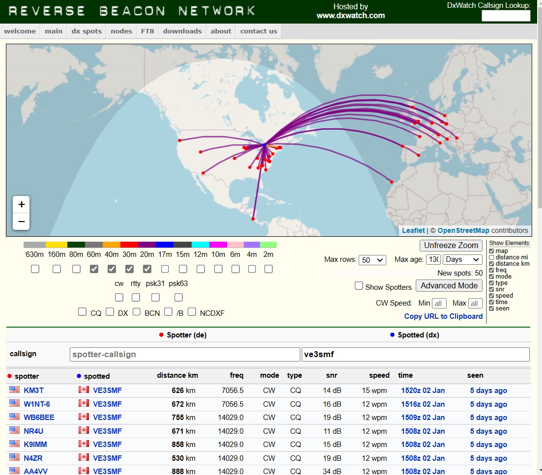
Figure 10: Sample Reverse Beacon Network propagation map for VE3SMF on 60m, 40m, 30m 20m bands for RBN in USA, Europe, Africa, and South America.
But wait, there is more! We have covered the basics of CW skimmers, Software Defined Radio and Reverse Beacon Network. What are some of the other cool uses of the RBN system?
There is interest locally in the Ottawa region in the use of Summits On The Air (SOTA) and Parks On The Air (POTA) activations. The RBN is an independent resource and not directly affiliated with SOTA and POTA. Having said that, the SOTA and POTA systems are capable of using RBN data in real time to create active spots. You must schedule or “add” your activation with POTA or “create” an alert with SOTA. If you have not scheduled your activation on-line BEFORE you activate, the RBN will still post your CW call on the RBN system, but it will not be picked up by the SOTA/POTA spotting systems. The SOTA/POTA systems need to know the date, times (+/-) and which park or summit that you plan to activate.
Why is this important? This process permits you to activate on SOTA/POTA when you are at your pre-planned activation location without the use of the internet/cell phone. For remote locations this can be one of the few methods to quickly activate. You can still call CQ POTA, make a contact, and hopefully find someone who can correctly make a post on the SOTA/POTA systems on your behalf. It does require some pre-planning and hopefully finding someone who already knows how to correctly post the required data on-line. See Figure 11 and 12, for what POTA and SOTA activation look like on line. Complete details on How to use the reverse Beacon Network (RBN) for automatic POTA and SOTA spotting are available at: https://qrper.com/2022/04/how-to-use-the-reverse-beacon-network-rbn-for-automatic-pota-and-sota-spotting/
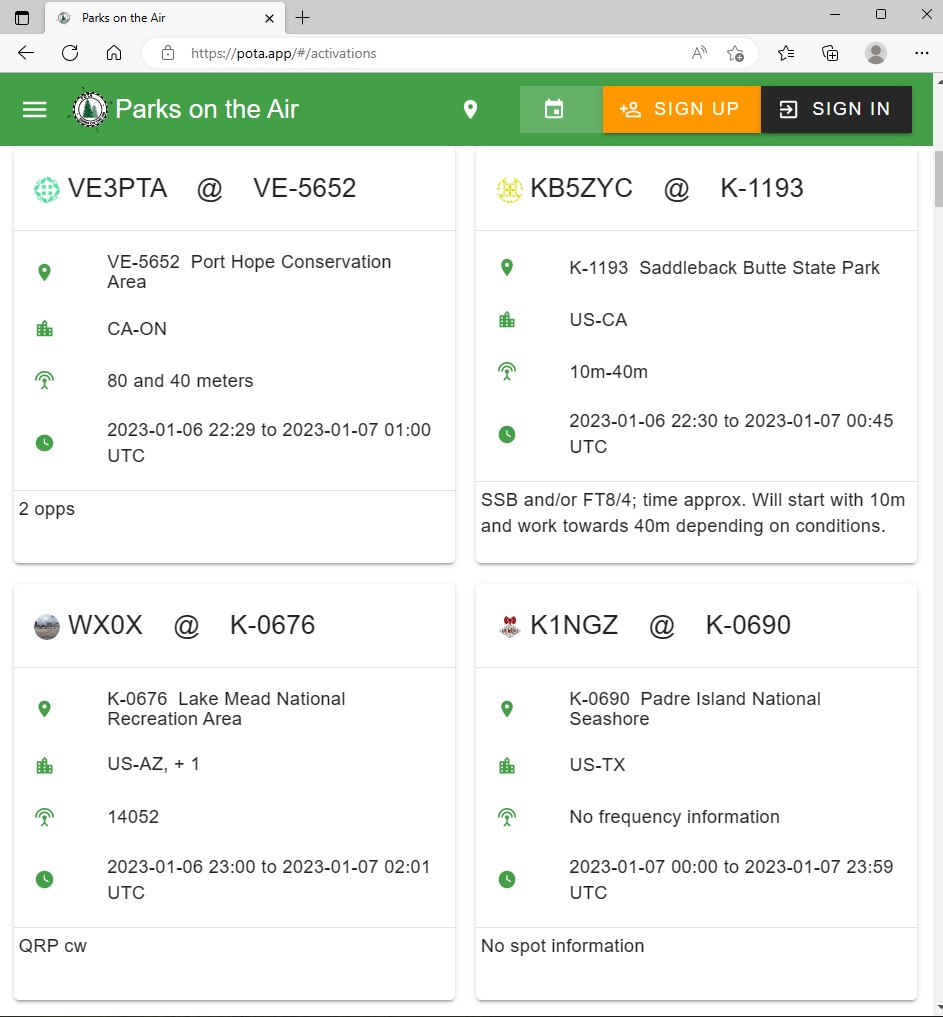
Figure 11: Sample Parks On The Air activation post by VE3PTA using the POTA App for activation Port Hope Conservation Area in Ontario on 40/80 m bands for 2023-01-06 22:29 to 2023-01-07 01:00 UTC.

Figure 12: Sample Summits On The Air post by VE2EO who was active on 21 MHz CW, 14 MHz CW, 7 MHz CW and 7 MHz SSB on Mont Bear in Quebec.
Stuart VE3SMF
Appears in: Rambler Vol. 65, Issue 5 January 2023