
In this article I will provide a brief update on the amplifier’s build progress.
Like many of you, I tend to reserve most of my amateur radio construction projects for the cold winter months when the quiet and peace of winter tends to provide me with greater patience and inspiration. Having said that, not much has happened on the amplifier since the spring.
I have restarted the project in the last week of November by starting on the construction of a matching 1600-Watt fan-cooled dummy load (DL). I needed the DL in order to proceed with the testing phase of the project. The DL is based on two Diconex brand, 800 watt, 100 Ohm, stripline RF resistors, model 39-0062. Diconex is a French company located in Andilly in France. I purchased them from an authorized reseller, Radio 741, located in Greece. They were approximately $80 each and shipping(mail) was about $10. They arrive at my door in about three weeks.
My intent was to build this DL to match the existing amplifier and power supply cases. I also wanted it to be controlled, monitored, and powered (fans) from the amplifier touch screen and power supply. It will be connected to a dedicated and switchable full power RF output connector on the back of the amplifier so that it can be selected and placed in circuit using the amplifier touch screen controller. I intend to use a dedicated Arduino Nano mounted in the case to operate the three temperature controlled PWM variable speed cooling fans and well as provide basic RF power measurements.
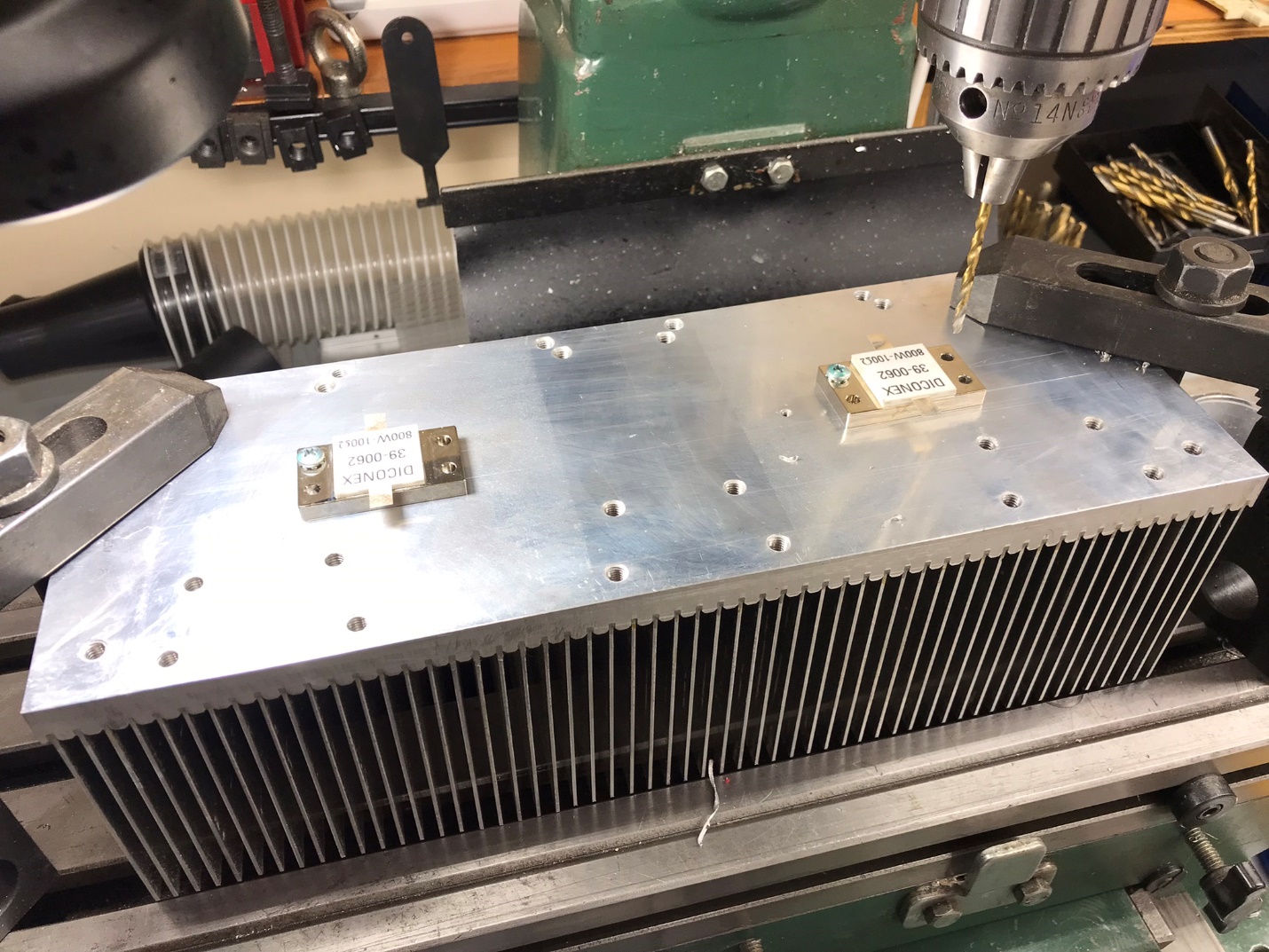
From time to time on rainy days over the past few months I experimented with the DL using inexpensive used 100W 50 ohm stripline resistors purchased on eBay for about $25. My experiments revealed that the DL SWR values were greatly affected based on their relative placement on the heatsink and the routing of the interconnecting wiring and/bussing. Simplifying the design by using only two 800-watt resistors as mounted in the following picture (see Photo 1) gave me the best results.
The resistors have been mounted on a repurposed aluminum heat sink with a base plate measuring ½” thick by 5” wide and 14” long. There are a total of 70 fins measuring 3.5 by 5 inches attached to the base plate. A total of eight holes were drilled and tapped to mount the resistors securely. I applied thermal paste before final mounting.
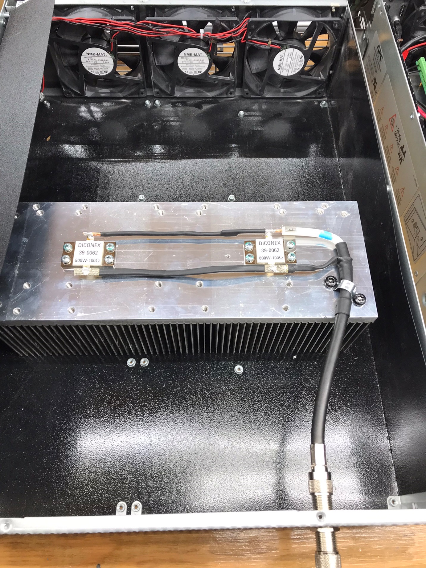
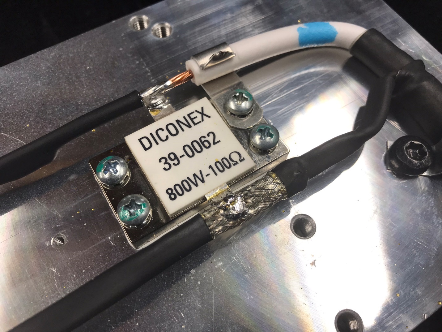
I used LMR-400 Ultra Flex to connect the resistors in parallel to give me a 1600 watt 50 ohm DL. You will note that the interconnections between the two resistors were made with the braid and the centre conductor of the LMR 400, see Photo 2 and Photo 3. This proved to provide good results. I am NOT an RF engineer or expert and came to this configuration after several tests by trial and error.
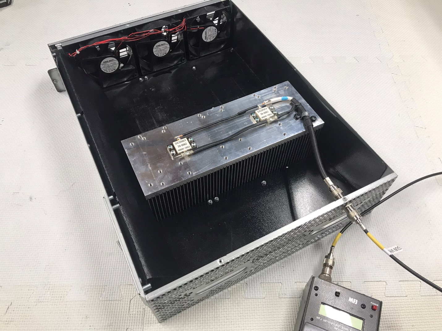
My MFJ-269 antenna analyzer displayed a consistent 50 ohm value throughout the 160 m to 6m operating range of the amplifier, see Photo 4. The 269 reported SWR values of 1.0 up to 12 MHz, and then 1.1 to 50 MHz.
I will report back as additional progress is made. If you have any questions or comments, please feel free to reach out to me at ve3boe@rac.ca.
73, Marc, VE3BOE
By: Marc VE3BOE
Appears in: Rambler Vol. 65, Issue 4 December 2022